Roberto
-
Numero contenuti
120 -
Iscritto
-
Ultima visita
Tipo di contenuto
Profili
Articoli
Introduzione alla stampa 3D
Database materiali
Forum
Calendario
Blogs
Gallery
Download
Store
Tutti i contenuti di Roberto
-
Conviene comprare solo PLA o anche ABS. Per i settaggi di stampa resta tutto uguale varia solo nei gradi? Per il PLA che ho usato fino adesso in prova andavo a 200 con piatto a 70 è giusto? Per l'ABS quanti gradi ci volgiono ho letto tra i 230 -250.
-
ho visto che reprapworld ha costi buoni tu quale prendi già che lo hai sperimentato . grazie
-
Collegamento display
Roberto ha risposto a Roberto nella discussione Problemi generici o di qualità di stampa
Quindi non si deve scaricare nessun file e ricarcarlo in marlin? Non ricordo dove ho letto di un file da scaricare prima di apportare modifiche al marlin. -
uso filo da 1,75 non da 3 anzi mi dici che ne pensi di questo filo che devo prenderlo? http://www.amazon.it/SainSmart-millimetri-fluoresceina-Replicator-Solidoodle/dp/B00H8MXASM/ref=sr_1_3?ie=UTF8&qid=1409753326&sr=8-3&keywords=pla#productDetails grazie
-
#define DEFAULT_AXIS_STEPS_PER_UNIT {80,80,4000,1550}#define DEFAULT_MAX_FEEDRATE {400, 400, 1, 45}#define DEFAULT_MAX_ACCELERATION {5000,6000,10,5000}#define DEFAULT_ACCELERATION 1000 #define DEFAULT_RETRACT_ACCELERATION 2000quindi il settaggio 80,80,4000,1550 lo devo modificare. Il 1550 devo ricalcolarlo Puo essere l'hobbed bolt che non porta il materiale giù (questo l'ho fatto io modificando un perno da 8 mm)
-
Collegamento display
Roberto ha risposto a Roberto nella discussione Problemi generici o di qualità di stampa
Nessuno riesce ad aiutarmi sul display? -
Leouz ti faccio vedere due immagini di cose stampate, come mai mi buca e stampa male quale può essere la causa, dove si può vedere un settaggio per Cura valido. Il piatto riscaldato è a 70 devo portarlo più alto? Come si vede nelle foto parte male a volte non riesce ad aderire la partenza e poi alla fine crea dei vuoti ciao grazie

-
problema risolto ho reinstallato Cura e ora funziona, anche facendo il gcode e portandolo in Repetier funziona la temperatura cambia
-
dunque carico il file stl in Cura lo setto a 250 (esempio) dopo faccio il gcode Quando carico il gcose in repetier non sale oltre i 200 e nel diagramma mi porta massimo 200. Se invece faccio da repetier e manualmente lo porto a 250(esempio) il diagramma mi arriva alla temperatura e anche i gradi.
-
Collegamento display
Roberto ha risposto a Roberto nella discussione Problemi generici o di qualità di stampa
REPRAP_DISCOUNT_SMART_CONTROLLER sul display c'è questo e nel Marlin ci sta #if defined (REPRAP_DISCOUNT_FULL_GRAPHIC_SMART_CONTROLLER) #define DOGLCD #define U8GLIB_ST7920 #define REPRAP_DISCOUNT_SMART_CONTROLLER #endif #if defined(ULTIMAKERCONTROLLER) || defined(REPRAP_DISCOUNT_SMART_CONTROLLER) || defined(G3D_PANEL) #define ULTIPANEL #define NEWPANEL #endif quindi devo solocolegarlo? grazie -
Ma la temperatura non supera proprio i 200 lo leggo da repetier usando il gcode di cura,con il diagramma arriva fino a 200 non segna oltre
-
Collegamento display
Roberto ha pubblicato una discussione in Problemi generici o di qualità di stampa
Ciao apro una nuova discussione. Il display viene montato sulla ramps, nel mio caso ramps 1.4 con il suo alloggio e cavetti di riferimento. Si devono apportare modifiche al Marlin, altrimenti non funziona giusto? Il mio display è completo di SD cosa altro devo fare per farlo funzionare? grazie -
Si i calcoli li ho rifatti appunto x-y è andato bene resta la z ho barre filettate da 0,5 il calcolo che ho fatto è 200*16 /25.4*18 dove la barra filettata è 5/16 (18 filetti per police quindi 25,.4/18=1.411) 200+16/25.4+18 =2267,71 Il filo non è abs comunque provo come mi hai detto ( per l'ABS ci vuole il piatto riscaldato giusto?) Per Cura è strana la cosa non mi sale la temperatura oltre i 200 ( era stata la prova appena ho cambiato il filo, pensavo che era ABS e che serviva aumentare i gradi, quindi più di 200. Perchè non attacca sul piano quando estrude?
-
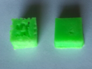
Ciao Leouz rieccomi scusa il ritardo sugli aggiornamenti. Ho fatto un po di prove di stampa il risultato è questo: #define DEFAULT_AXIS_STEPS_PER_UNIT {75,75,3500,775} #define DEFAULT_MAX_FEEDRATE {400, 400, 1, 45} #define DEFAULT_MAX_ACCELERATION {5000,6000,10,5000} #define DEFAULT_ACCELERATION 1000 #define DEFAULT_RETRACT_ACCELERATION 2000 con questo settaggio ho avuto il cubetto di sx doveva misurare 1 cm per lato e mi dava 0,8 X - 0,8 Y - 0,7 Z mm Ho cambiato il settaggio rifacendo i calcoli in: #define DEFAULT_AXIS_STEPS_PER_UNIT {80,80,2267,1500} #define DEFAULT_MAX_FEEDRATE {400, 400, 1, 45} #define DEFAULT_MAX_ACCELERATION {5000,6000,10,5000} #define DEFAULT_ACCELERATION 1000 #define DEFAULT_RETRACT_ACCELERATION 2000 con questo settaggio ho avuto il cubetto di sx doveva misurare 1 cm per lato e mi dava 10 X - 10 Y - 0,5 Z mm ma più compatto come si vede nella foto di dx quindi cosa vuol dire che devo raddoppiare la Z? Ancora una domanda mi è finito il filo del pla e ne avevo un altro l'ho inserito e questo filo è diverso dall'altro non riesce ad attaccare sul piatto che devo fare. Ho messo anche la lacca ma non prende. Questo filo mi sembra migliore dell'altro piu rigido e resistente l'altro si spezzava solo a guardarlo. Ma il software Cura supera i 200 gradi? Volevo portarlo a 220 e più ma mi da nel gcode sempre 200 come mai ciao e grazie
-
ciao si ti invio gli ultimi sviluppi appena arriva il mio collega e amico, stiamo costruendo insieme la prusa grazie ti aggiornerò su tutto
-
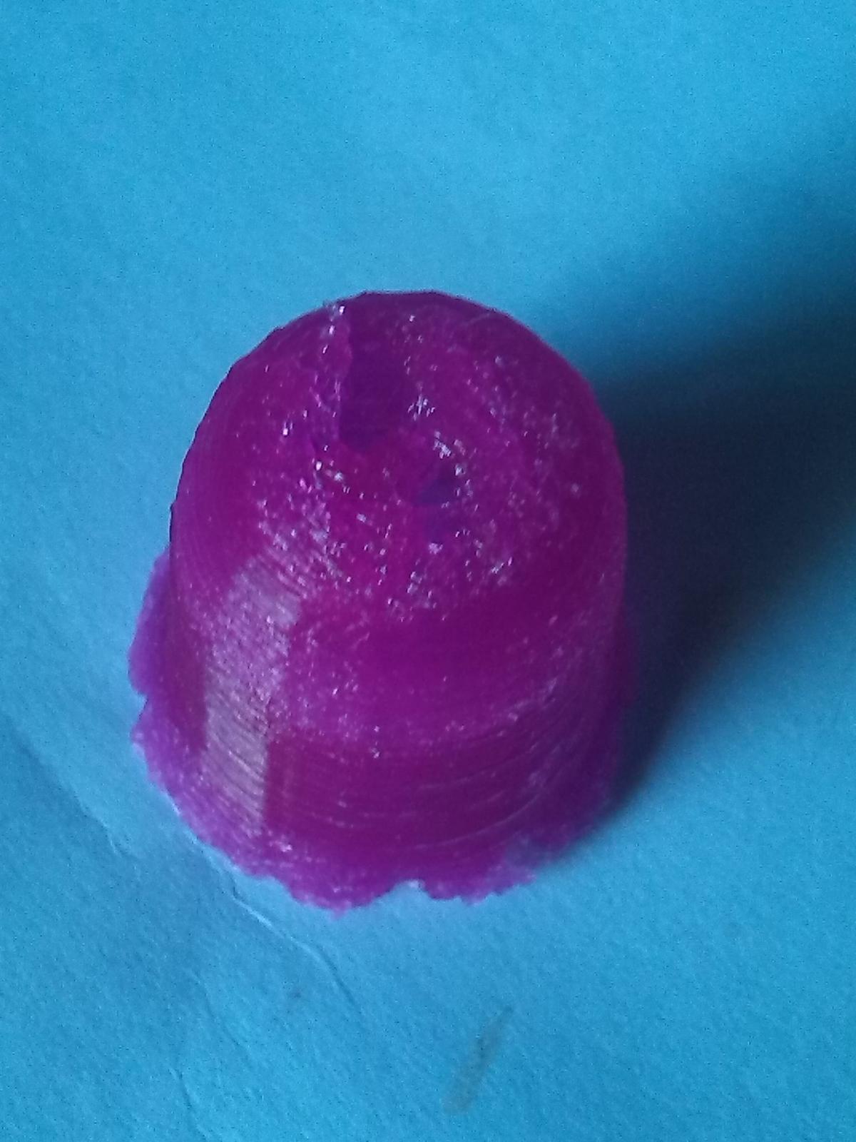
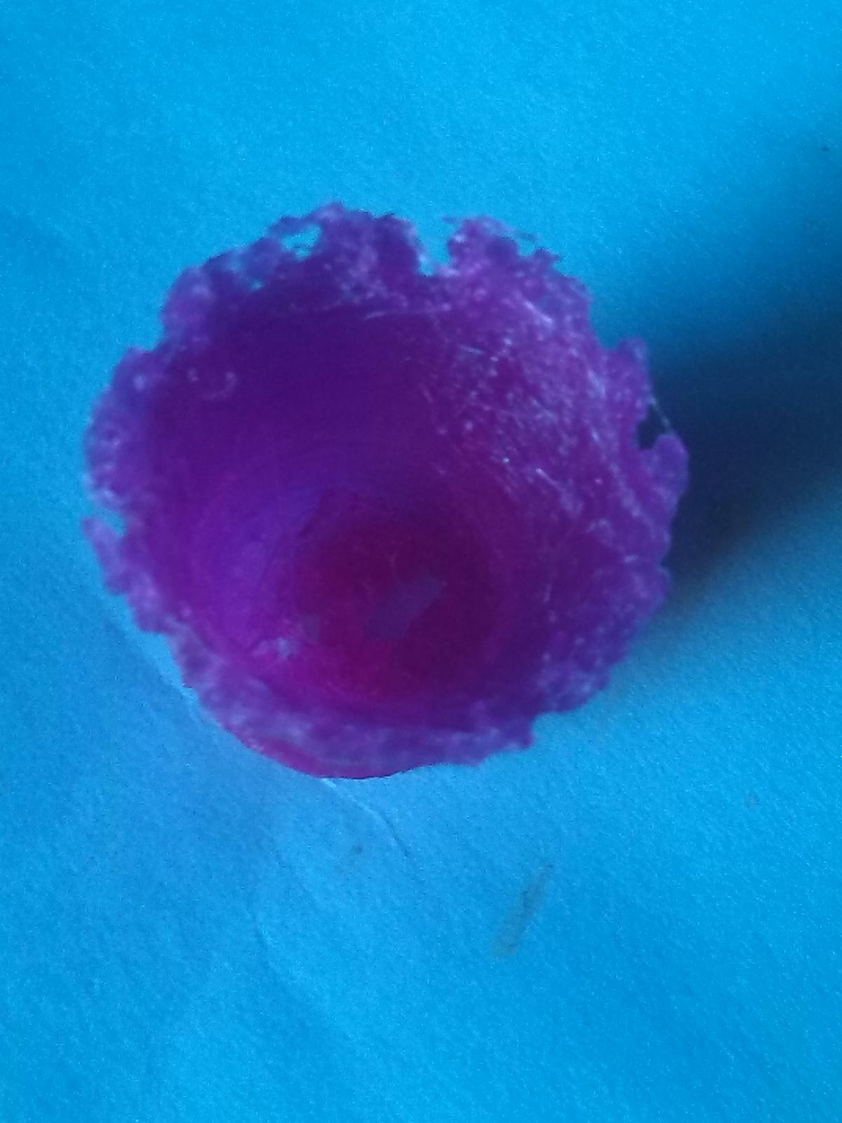
ciao Leouz Ieri ho rifatto il cubetto che avevo creato ti invio l'immagine. questa è la faccia finale di sopra questa quella di sotto sul piatto Ho regolato un po la pressione del filo stampando pla a 200. Avevo abbassato la temperatura a 180 e poi a 190 (vedevo che mi colava pla dall'uggello estrusore) ma il risultato era scarso non usciva pla. Ho cercato in marlin le regolazioni da fare come mi hai detto ma non sono riuscito a trovare le righe di riferimento. Ho misurato il filo in uscita e praticamente era al 50% di quello segnato in repetier nel senso che in repetier estrudevo 10mm invece il filo estruso era 5mm, ho fatto tante tacchettine ogni 5mm e appunto ogni volta che premevo su estrudi scendeva il filo di 5mm. Quali sono in marlin le righe di riferimento?
-
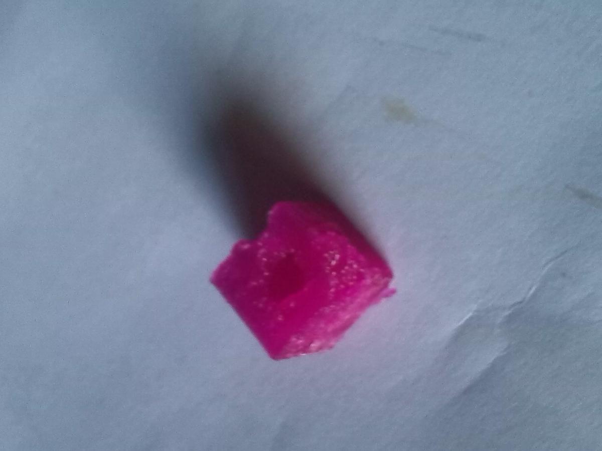
l'ho sbriciolato togliendolo magari lo rifaccio
-
Ciao rieccomi Cosa vai a stampare? PLA o ABS? Sto stampando con un po di PLA ricevuto insieme al materiale della stampante. Oggi ho fatto una prova di stampa. Ho fatto un cubetto con rhino e poi ho salvato il file in stl. Poi ho esportato il gcode per importarlo in repetier host Ho caricato il file in repetier e avviato il tutto. Ecco che và, prima raggiunge la home dei 3 assi, poi si posiziona al centro e comincia a stampare il cubetto. Un giusto settaggio per cura quale dovrebbe essere il cubetto è uscito un po fragile non compatto questi sono i dati che ho messo che ne dici?
-
Ciao Buon Ferragosto sto seguendo i passi come mi hai suggerito. faccio un passo indietro, ho settato i driver come nel post inserito qui: http://www.stampa3d-forum.it/guida-rego ... stepstick/ la vref iniziale era 0,64 ho portato i drivers a 0,3. Ho dovuto aumentare il driver dell'estrusore perchè non girava bene. Pensandoci bene e rileggendo il post di regolazione la vref per girare meglio ora è 0,75 quindi oltre i 0,64 iniziale, ( i motori che uso sono i nema 17 e le caratteristiche sono le stesse del post). Mi preoccupa la cosa che posso portare danno ai driver che ne pensi? Altro pensiero seguendo le istruzioni ho provato ad infilare il filo nell'estrusore per provare la temperatura ma ho la sensazione che non scende bene infilandolo, di solito mettendo il filo di quanto dovrebbe entrare nel hotend, ( ho avuto l'estrusore già montato e non vorrei che il buco dell'hotend non si infili con il buco dell'estrusore e il filo urti e non scende) è facile smontarlo dalla plastica per verificare il tutto? Ieri ho settato Cura e ho salvato un gcode volevo poi inserirlo in repetier,come carico il file non trovo da nessuna parte dove caricare il file gcode. Grazie Buon ferragosto
-
ciao il motore si è mosso solo dopo aver modificato la riga in marlin che mi hai suggerito prima non si muoveva proprio. Ma forse è meglio che mi dai una dritta sulla cosa. L'estrusore quando raggiunge la temperatura dovrebbe partire da solo anche senza che io gli clicchi su estrudi? Quello che ho fatto dopo aver fatto la meccanica ho messo i motori e li ho fatti muovere manualmente da Repetier. Non ho mai messo il filo per tentare una estrusione. Volendo provare i passi sono: caricare un stl in Repetier, mettere un filo di prova e accendere l'estrusore? come vedi siamo proprio a zero e forse questo può servire a tanti come me. I motori sono tutti con una vref settata a 0,30 solo l'estrusore l'ho portato a 0,40 pensi sia basso? ciao e grazie per la pazienza
-
ho provato subito ad aumentare il drivers da 0,30 a 0,40, ma cliccando su estrudi o ritrai gira tremando non fluido anzi se clicco estrudi gira a dx ma su ritrai gira lo stesso a dx è normale?
-
Dai che forse ci siamo Bene modificando questa riga: // #define PREVENT_DANGEROUS_EXTRUDE il motore non parte raggiungendo la temperatura da solo ma cliccando su estrudi o ritrai sotto la temperatura si muove. Cosi deve funzionare? Se è così forse devo regolare un po il driver dell'estrusore perchè non è fluido aumentandolo un po che ne dici. Grazie
-
In repetier Host nella parte in basso dove scorrono tutti i codici vien fuori qualche messaggio di errore? il motore non sibila? non si scalda? ho staccato il motore dall'estrusore per capire se si muova o meno senza essere influenzato dagli ingranaggi di trasporto del filo, e il motore non si muove e nemmeno sibila e non si scalda. in riferimento : #define EXTRUDE_MINTEMP 170 l'ho modificato come dicevi in ://#define EXTRUDE_MINTEMP 170 e mi da errore ti allego l'immagine
-
2° parte //===========================================================================//=============================Mechanical Settings===========================//===========================================================================// Uncomment the following line to enable CoreXY kinematics// #define COREXY// coarse Endstop Settings#define ENDSTOPPULLUPS // Comment this out (using // at the start of the line) to disable the endstop pullup resistors#ifndef ENDSTOPPULLUPS // fine endstop settings: Individual pullups. will be ignored if ENDSTOPPULLUPS is defined #define ENDSTOPPULLUP_XMAX #define ENDSTOPPULLUP_YMAX #define ENDSTOPPULLUP_ZMAX #define ENDSTOPPULLUP_XMIN #define ENDSTOPPULLUP_YMIN // #define ENDSTOPPULLUP_ZMIN#endif#ifdef ENDSTOPPULLUPS #define ENDSTOPPULLUP_XMAX #define ENDSTOPPULLUP_YMAX #define ENDSTOPPULLUP_ZMAX #define ENDSTOPPULLUP_XMIN #define ENDSTOPPULLUP_YMIN #define ENDSTOPPULLUP_ZMIN#endif// The pullups are needed if you directly connect a mechanical endswitch between the signal and ground pins.const bool X_MIN_ENDSTOP_INVERTING = false; // set to true to invert the logic of the endstop.const bool Y_MIN_ENDSTOP_INVERTING = false; // set to true to invert the logic of the endstop.const bool Z_MIN_ENDSTOP_INVERTING = false; // set to true to invert the logic of the endstop.const bool X_MAX_ENDSTOP_INVERTING = false; // set to true to invert the logic of the endstop.const bool Y_MAX_ENDSTOP_INVERTING = false; // set to true to invert the logic of the endstop.const bool Z_MAX_ENDSTOP_INVERTING = false; // set to true to invert the logic of the endstop.//#define DISABLE_MAX_ENDSTOPS//#define DISABLE_MIN_ENDSTOPS// Disable max endstops for compatibility with endstop checking routine#if defined(COREXY) && !defined(DISABLE_MAX_ENDSTOPS) #define DISABLE_MAX_ENDSTOPS#endif// For Inverting Stepper Enable Pins (Active Low) use 0, Non Inverting (Active High) use 1#define X_ENABLE_ON 0#define Y_ENABLE_ON 0#define Z_ENABLE_ON 0#define E_ENABLE_ON 0 // For all extruders// Disables axis when it's not being used.#define DISABLE_X false#define DISABLE_Y false#define DISABLE_Z false#define DISABLE_E false // For all extruders#define DISABLE_INACTIVE_EXTRUDER true //disable only inactive extruders and keep active extruder enabled#define INVERT_X_DIR true // for Mendel set to false, for Orca set to true#define INVERT_Y_DIR false // for Mendel set to true, for Orca set to false#define INVERT_Z_DIR true // for Mendel set to false, for Orca set to true#define INVERT_E0_DIR false // for direct drive extruder v9 set to true, for geared extruder set to false#define INVERT_E1_DIR false // for direct drive extruder v9 set to true, for geared extruder set to false#define INVERT_E2_DIR false // for direct drive extruder v9 set to true, for geared extruder set to false// ENDSTOP SETTINGS:// Sets direction of endstops when homing; 1=MAX, -1=MIN#define X_HOME_DIR -1#define Y_HOME_DIR -1#define Z_HOME_DIR -1#define min_software_endstops true // If true, axis won't move to coordinates less than HOME_POS.#define max_software_endstops true // If true, axis won't move to coordinates greater than the defined lengths below.// Travel limits after homing#define X_MAX_POS 205#define X_MIN_POS 0#define Y_MAX_POS 205#define Y_MIN_POS 0#define Z_MAX_POS 200#define Z_MIN_POS 0#define X_MAX_LENGTH (X_MAX_POS - X_MIN_POS)#define Y_MAX_LENGTH (Y_MAX_POS - Y_MIN_POS)#define Z_MAX_LENGTH (Z_MAX_POS - Z_MIN_POS)//============================= Bed Auto Leveling ===========================//#define ENABLE_AUTO_BED_LEVELING // Delete the comment to enable (remove // at the start of the line)#ifdef ENABLE_AUTO_BED_LEVELING// There are 2 different ways to pick the X and Y locations to probe:// - "grid" mode// Probe every point in a rectangular grid// You must specify the rectangle, and the density of sample points// This mode is preferred because there are more measurements.// It used to be called ACCURATE_BED_LEVELING but "grid" is more descriptive// - "3-point" mode// Probe 3 arbitrary points on the bed (that aren't colinear)// You must specify the X & Y coordinates of all 3 points #define AUTO_BED_LEVELING_GRID // with AUTO_BED_LEVELING_GRID, the bed is sampled in a // AUTO_BED_LEVELING_GRID_POINTSxAUTO_BED_LEVELING_GRID_POINTS grid // and least squares solution is calculated // Note: this feature occupies 10'206 byte #ifdef AUTO_BED_LEVELING_GRID // set the rectangle in which to probe #define LEFT_PROBE_BED_POSITION 15 #define RIGHT_PROBE_BED_POSITION 170 #define BACK_PROBE_BED_POSITION 180 #define FRONT_PROBE_BED_POSITION 20 // set the number of grid points per dimension // I wouldn't see a reason to go above 3 (=9 probing points on the bed) #define AUTO_BED_LEVELING_GRID_POINTS 2 #else // not AUTO_BED_LEVELING_GRID // with no grid, just probe 3 arbitrary points. A simple cross-product // is used to esimate the plane of the print bed #define ABL_PROBE_PT_1_X 15 #define ABL_PROBE_PT_1_Y 180 #define ABL_PROBE_PT_2_X 15 #define ABL_PROBE_PT_2_Y 20 #define ABL_PROBE_PT_3_X 170 #define ABL_PROBE_PT_3_Y 20 #endif // AUTO_BED_LEVELING_GRID // these are the offsets to the probe relative to the extruder tip (Hotend - Probe) #define X_PROBE_OFFSET_FROM_EXTRUDER -25 #define Y_PROBE_OFFSET_FROM_EXTRUDER -29 #define Z_PROBE_OFFSET_FROM_EXTRUDER -12.35 #define Z_RAISE_BEFORE_HOMING 4 // (in mm) Raise Z before homing (G28) for Probe Clearance. // Be sure you have this distance over your Z_MAX_POS in case #define XY_TRAVEL_SPEED 8000 // X and Y axis travel speed between probes, in mm/min #define Z_RAISE_BEFORE_PROBING 15 //How much the extruder will be raised before traveling to the first probing point. #define Z_RAISE_BETWEEN_PROBINGS 5 //How much the extruder will be raised when traveling from between next probing points //If defined, the Probe servo will be turned on only during movement and then turned off to avoid jerk //The value is the delay to turn the servo off after powered on - depends on the servo speed; 300ms is good value, but you can try lower it. // You MUST HAVE the SERVO_ENDSTOPS defined to use here a value higher than zero otherwise your code will not compile.// #define PROBE_SERVO_DEACTIVATION_DELAY 300//If you have enabled the Bed Auto Leveling and are using the same Z Probe for Z Homing,//it is highly recommended you let this Z_SAFE_HOMING enabled!!! #define Z_SAFE_HOMING // This feature is meant to avoid Z homing with probe outside the bed area. // When defined, it will: // - Allow Z homing only after X and Y homing AND stepper drivers still enabled // - If stepper drivers timeout, it will need X and Y homing again before Z homing // - Position the probe in a defined XY point before Z Homing when homing all axis (G28) // - Block Z homing only when the probe is outside bed area. #ifdef Z_SAFE_HOMING #define Z_SAFE_HOMING_X_POINT (X_MAX_LENGTH/2) // X point for Z homing when homing all axis (G28) #define Z_SAFE_HOMING_Y_POINT (Y_MAX_LENGTH/2) // Y point for Z homing when homing all axis (G28) #endif#endif // ENABLE_AUTO_BED_LEVELING// The position of the homing switches//#define MANUAL_HOME_POSITIONS // If defined, MANUAL_*_HOME_POS below will be used//#define BED_CENTER_AT_0_0 // If defined, the center of the bed is at (X=0, Y=0)//Manual homing switch locations:// For deltabots this means top and center of the Cartesian print volume.#define MANUAL_X_HOME_POS 0#define MANUAL_Y_HOME_POS 0#define MANUAL_Z_HOME_POS 0//#define MANUAL_Z_HOME_POS 402 // For delta: Distance between nozzle and print surface after homing.//// MOVEMENT SETTINGS#define NUM_AXIS 4 // The axis order in all axis related arrays is X, Y, Z, E#define HOMING_FEEDRATE {25*60, 25*60, 2*60, 0} // set the homing speeds (mm/min)// default settings#define DEFAULT_AXIS_STEPS_PER_UNIT {77,75,3400,775} // default steps per unit for Ultimaker#define DEFAULT_MAX_FEEDRATE {400, 400, 1, 45} // (mm/sec)#define DEFAULT_MAX_ACCELERATION {5000,6000,10,5000} // X, Y, Z, E maximum start speed for accelerated moves. E default values are good for Skeinforge 40+, for older versions raise them a lot.#define DEFAULT_ACCELERATION 1000 // X, Y, Z and E max acceleration in mm/s^2 for printing moves#define DEFAULT_RETRACT_ACCELERATION 2000 // X, Y, Z and E max acceleration in mm/s^2 for retracts// Offset of the extruders (uncomment if using more than one and relying on firmware to position when changing).// The offset has to be X=0, Y=0 for the extruder 0 hotend (default extruder).// For the other hotends it is their distance from the extruder 0 hotend.// #define EXTRUDER_OFFSET_X {0.0, 20.00} // (in mm) for each extruder, offset of the hotend on the X axis// #define EXTRUDER_OFFSET_Y {0.0, 5.00} // (in mm) for each extruder, offset of the hotend on the Y axis// The speed change that does not require acceleration (i.e. the software might assume it can be done instantaneously)#define DEFAULT_XYJERK 20.0 // (mm/sec)#define DEFAULT_ZJERK 0.4 // (mm/sec)#define DEFAULT_EJERK 5.0 // (mm/sec)//===========================================================================//=============================Additional Features===========================//===========================================================================// Custom M code points#define CUSTOM_M_CODES#ifdef CUSTOM_M_CODES #define CUSTOM_M_CODE_SET_Z_PROBE_OFFSET 851 #define Z_PROBE_OFFSET_RANGE_MIN -15 #define Z_PROBE_OFFSET_RANGE_MAX -5#endif// EEPROM// The microcontroller can store settings in the EEPROM, e.g. max velocity...// M500 - stores parameters in EEPROM// M501 - reads parameters from EEPROM (if you need reset them after you changed them temporarily).// M502 - reverts to the default "factory settings". You still need to store them in EEPROM afterwards if you want to.//define this to enable EEPROM support//#define EEPROM_SETTINGS//to disable EEPROM Serial responses and decrease program space by ~1700 byte: comment this out:// please keep turned on if you can.//#define EEPROM_CHITCHAT// Preheat Constants#define PLA_PREHEAT_HOTEND_TEMP 180#define PLA_PREHEAT_HPB_TEMP 70#define PLA_PREHEAT_FAN_SPEED 255 // Insert Value between 0 and 255#define ABS_PREHEAT_HOTEND_TEMP 240#define ABS_PREHEAT_HPB_TEMP 100#define ABS_PREHEAT_FAN_SPEED 255 // Insert Value between 0 and 255//LCD and SD support//#define ULTRA_LCD //general LCD support, also 16x2//#define DOGLCD // Support for SPI LCD 128x64 (Controller ST7565R graphic Display Family)//#define SDSUPPORT // Enable SD Card Support in Hardware Console//#define SDSLOW // Use slower SD transfer mode (not normally needed - uncomment if you're getting volume init error)//#define SD_CHECK_AND_RETRY // Use CRC checks and retries on the SD communication//#define ENCODER_PULSES_PER_STEP 1 // Increase if you have a high resolution encoder//#define ENCODER_STEPS_PER_MENU_ITEM 5 // Set according to ENCODER_PULSES_PER_STEP or your liking//#define ULTIMAKERCONTROLLER //as available from the Ultimaker online store.//#define ULTIPANEL //the UltiPanel as on Thingiverse//#define LCD_FEEDBACK_FREQUENCY_HZ 1000 // this is the tone frequency the buzzer plays when on UI feedback. ie Screen Click//#define LCD_FEEDBACK_FREQUENCY_DURATION_MS 100 // the duration the buzzer plays the UI feedback sound. ie Screen Click// The MaKr3d Makr-Panel with graphic controller and SD support// http://reprap.org/wiki/MaKr3d_MaKrPanel//#define MAKRPANEL// The RepRapDiscount Smart Controller (white PCB)// http://reprap.org/wiki/RepRapDiscount_Smart_Controller//#define REPRAP_DISCOUNT_SMART_CONTROLLER// The GADGETS3D G3D LCD/SD Controller (blue PCB)// http://reprap.org/wiki/RAMPS_1.3/1.4_GADGETS3D_Shield_with_Panel//#define G3D_PANEL// The RepRapDiscount FULL GRAPHIC Smart Controller (quadratic white PCB)// http://reprap.org/wiki/RepRapDiscount_Full_Graphic_Smart_Controller//// ==> REMEMBER TO INSTALL U8glib to your ARDUINO library folder: http://code.google.com/p/u8glib/wiki/u8glib//#define REPRAP_DISCOUNT_FULL_GRAPHIC_SMART_CONTROLLER// The RepRapWorld REPRAPWORLD_KEYPAD v1.1// http://reprapworld.com/?products_details&products_id=202&cPath=1591_1626//#define REPRAPWORLD_KEYPAD//#define REPRAPWORLD_KEYPAD_MOVE_STEP 10.0 // how much should be moved when a key is pressed, eg 10.0 means 10mm per click// The Elefu RA Board Control Panel// http://www.elefu.com/index.php?route=product/product&product_id=53// REMEMBER TO INSTALL LiquidCrystal_I2C.h in your ARUDINO library folder: https://github.com/kiyoshigawa/LiquidCrystal_I2C//#define RA_CONTROL_PANEL//automatic expansion#if defined (MAKRPANEL) #define DOGLCD #define SDSUPPORT #define ULTIPANEL #define NEWPANEL #define DEFAULT_LCD_CONTRAST 17#endif#if defined (REPRAP_DISCOUNT_FULL_GRAPHIC_SMART_CONTROLLER) #define DOGLCD #define U8GLIB_ST7920 #define REPRAP_DISCOUNT_SMART_CONTROLLER#endif#if defined(ULTIMAKERCONTROLLER) || defined(REPRAP_DISCOUNT_SMART_CONTROLLER) || defined(G3D_PANEL) #define ULTIPANEL #define NEWPANEL#endif#if defined(REPRAPWORLD_KEYPAD) #define NEWPANEL #define ULTIPANEL#endif#if defined(RA_CONTROL_PANEL) #define ULTIPANEL #define NEWPANEL #define LCD_I2C_TYPE_PCA8574 #define LCD_I2C_ADDRESS 0x27 // I2C Address of the port expander#endif//I2C PANELS//#define LCD_I2C_SAINSMART_YWROBOT#ifdef LCD_I2C_SAINSMART_YWROBOT // This uses the LiquidCrystal_I2C library ( https://bitbucket.org/fmalpartida/new-liquidcrystal/wiki/Home ) // Make sure it is placed in the Arduino libraries directory. #define LCD_I2C_TYPE_PCF8575 #define LCD_I2C_ADDRESS 0x27 // I2C Address of the port expander #define NEWPANEL #define ULTIPANEL#endif// PANELOLU2 LCD with status LEDs, separate encoder and click inputs//#define LCD_I2C_PANELOLU2#ifdef LCD_I2C_PANELOLU2 // This uses the LiquidTWI2 library v1.2.3 or later ( https://github.com/lincomatic/LiquidTWI2 ) // Make sure the LiquidTWI2 directory is placed in the Arduino or Sketchbook libraries subdirectory. // (v1.2.3 no longer requires you to define PANELOLU in the LiquidTWI2.h library header file) // Note: The PANELOLU2 encoder click input can either be directly connected to a pin // (if BTN_ENC defined to != -1) or read through I2C (when BTN_ENC == -1). #define LCD_I2C_TYPE_MCP23017 #define LCD_I2C_ADDRESS 0x20 // I2C Address of the port expander #define LCD_USE_I2C_BUZZER //comment out to disable buzzer on LCD #define NEWPANEL #define ULTIPANEL #ifndef ENCODER_PULSES_PER_STEP #define ENCODER_PULSES_PER_STEP 4 #endif #ifndef ENCODER_STEPS_PER_MENU_ITEM #define ENCODER_STEPS_PER_MENU_ITEM 1 #endif #ifdef LCD_USE_I2C_BUZZER #define LCD_FEEDBACK_FREQUENCY_HZ 1000 #define LCD_FEEDBACK_FREQUENCY_DURATION_MS 100 #endif#endif// Panucatt VIKI LCD with status LEDs, integrated click & L/R/U/P buttons, separate encoder inputs//#define LCD_I2C_VIKI#ifdef LCD_I2C_VIKI // This uses the LiquidTWI2 library v1.2.3 or later ( https://github.com/lincomatic/LiquidTWI2 ) // Make sure the LiquidTWI2 directory is placed in the Arduino or Sketchbook libraries subdirectory. // Note: The pause/stop/resume LCD button pin should be connected to the Arduino // BTN_ENC pin (or set BTN_ENC to -1 if not used) #define LCD_I2C_TYPE_MCP23017 #define LCD_I2C_ADDRESS 0x20 // I2C Address of the port expander #define LCD_USE_I2C_BUZZER //comment out to disable buzzer on LCD (requires LiquidTWI2 v1.2.3 or later) #define NEWPANEL #define ULTIPANEL#endif// Shift register panels// ---------------------// 2 wire Non-latching LCD SR from:// https://bitbucket.org/fmalpartida/new-liquidcrystal/wiki/schematics#!shiftregister-connection//#define SR_LCD#ifdef SR_LCD #define SR_LCD_2W_NL // Non latching 2 wire shift register //#define NEWPANEL#endif#ifdef ULTIPANEL// #define NEWPANEL //enable this if you have a click-encoder panel #define SDSUPPORT #define ULTRA_LCD #ifdef DOGLCD // Change number of lines to match the DOG graphic display #define LCD_WIDTH 20 #define LCD_HEIGHT 5 #else #define LCD_WIDTH 20 #define LCD_HEIGHT 4 #endif#else //no panel but just LCD #ifdef ULTRA_LCD #ifdef DOGLCD // Change number of lines to match the 128x64 graphics display #define LCD_WIDTH 20 #define LCD_HEIGHT 5 #else #define LCD_WIDTH 16 #define LCD_HEIGHT 2 #endif #endif#endif// default LCD contrast for dogm-like LCD displays#ifdef DOGLCD# ifndef DEFAULT_LCD_CONTRAST# define DEFAULT_LCD_CONTRAST 32# endif#endif// Increase the FAN pwm frequency. Removes the PWM noise but increases heating in the FET/Arduino//#define FAST_PWM_FAN// Temperature status LEDs that display the hotend and bet temperature.// If all hotends and bed temperature and temperature setpoint are < 54C then the BLUE led is on.// Otherwise the RED led is on. There is 1C hysteresis.//#define TEMP_STAT_LEDS// Use software PWM to drive the fan, as for the heaters. This uses a very low frequency// which is not ass annoying as with the hardware PWM. On the other hand, if this frequency// is too low, you should also increment SOFT_PWM_SCALE.//#define FAN_SOFT_PWM// Incrementing this by 1 will double the software PWM frequency,// affecting heaters, and the fan if FAN_SOFT_PWM is enabled.// However, control resolution will be halved for each increment;// at zero value, there are 128 effective control positions.#define SOFT_PWM_SCALE 0// M240 Triggers a camera by emulating a Canon RC-1 Remote// Data from: http://www.doc-diy.net/photo/rc-1_hacked/// #define PHOTOGRAPH_PIN 23// SF send wrong arc g-codes when using Arc Point as fillet procedure//#define SF_ARC_FIX// Support for the BariCUDA Paste Extruder.//#define BARICUDA//define BlinkM/CyzRgb Support//#define BLINKM/*********************************************************************\* R/C SERVO support* Sponsored by TrinityLabs, Reworked by codexmas**********************************************************************/// Number of servos//// If you select a configuration below, this will receive a default value and does not need to be set manually// set it manually if you have more servos than extruders and wish to manually control some// leaving it undefined or defining as 0 will disable the servo subsystem// If unsure, leave commented / disabled////#define NUM_SERVOS 3 // Servo index starts with 0 for M280 command// Servo Endstops//// This allows for servo actuated endstops, primary usage is for the Z Axis to eliminate calibration or bed height changes.// Use M206 command to correct for switch height offset to actual nozzle height. Store that setting with M500.////#define SERVO_ENDSTOPS {-1, -1, 0} // Servo index for X, Y, Z. Disable with -1//#define SERVO_ENDSTOP_ANGLES {0,0, 0,0, 70,0} // X,Y,Z Axis Extend and Retract angles#include "Configuration_adv.h"#include "thermistortables.h"#endif //__CONFIGURATION_H
-
ti inserisco il file in due post perchè supera i caratteri che arrivano fino a 20000 #ifndef CONFIGURATION_H#define CONFIGURATION_H// This configuration file contains the basic settings.// Advanced settings can be found in Configuration_adv.h// BASIC SETTINGS: select your board type, temperature sensor type, axis scaling, and endstop configuration//===========================================================================//============================= DELTA Printer ===============================//===========================================================================// For a Delta printer replace the configuration files with the files in the// example_configurations/delta directory.//// User-specified version info of this build to display in [Pronterface, etc] terminal window during// startup. Implementation of an idea by Prof Braino to inform user that any changes made to this// build by the user have been successfully uploaded into firmware.#define STRING_VERSION_CONFIG_H __DATE__ " " __TIME__ // build date and time#define STRING_CONFIG_H_AUTHOR "(none, default config)" // Who made the changes.// SERIAL_PORT selects which serial port should be used for communication with the host.// This allows the connection of wireless adapters (for instance) to non-default port pins.// Serial port 0 is still used by the Arduino bootloader regardless of this setting.#define SERIAL_PORT 0// This determines the communication speed of the printer// This determines the communication speed of the printer#define BAUDRATE 250000// This enables the serial port associated to the Bluetooth interface//#define BTENABLED // Enable BT interface on AT90USB devices//// The following define selects which electronics board you have. Please choose the one that matches your setup// 10 = Gen7 custom (Alfons3 Version) "https://github.com/Alfons3/Generation_7_Electronics"// 11 = Gen7 v1.1, v1.2 = 11// 12 = Gen7 v1.3// 13 = Gen7 v1.4// 2 = Cheaptronic v1.0// 20 = Sethi 3D_1// 3 = MEGA/RAMPS up to 1.2 = 3// 33 = RAMPS 1.3 / 1.4 (Power outputs: Extruder, Fan, Bed)// 34 = RAMPS 1.3 / 1.4 (Power outputs: Extruder0, Extruder1, Bed)// 35 = RAMPS 1.3 / 1.4 (Power outputs: Extruder, Fan, Fan)// 4 = Duemilanove w/ ATMega328P pin assignment// 5 = Gen6// 51 = Gen6 deluxe// 6 = Sanguinololu < 1.2// 62 = Sanguinololu 1.2 and above// 63 = Melzi// 64 = STB V1.1// 65 = Azteeg X1// 66 = Melzi with ATmega1284 (MaKr3d version)// 67 = Azteeg X3// 68 = Azteeg X3 Pro// 7 = Ultimaker// 71 = Ultimaker (Older electronics. Pre 1.5.4. This is rare)// 72 = Ultimainboard 2.x (Uses TEMP_SENSOR 20)// 77 = 3Drag Controller// 8 = Teensylu// 80 = Rumba// 81 = Printrboard (AT90USB1286)// 82 = Brainwave (AT90USB646)// 83 = SAV Mk-I (AT90USB1286)// 84 = Teensy++2.0 (AT90USB1286) // CLI compile: DEFINES=AT90USBxx_TEENSYPP_ASSIGNMENTS HARDWARE_MOTHERBOARD=84 make// 9 = Gen3+// 70 = Megatronics// 701= Megatronics v2.0// 702= Minitronics v1.0// 90 = Alpha OMCA board// 91 = Final OMCA board// 301= Rambo// 21 = Elefu Ra Board (v3)// 88 = 5DPrint D8 Driver Board#ifndef MOTHERBOARD#define MOTHERBOARD 33#endif// Define this to set a custom name for your generic Mendel,// #define CUSTOM_MENDEL_NAME "This Mendel"// Define this to set a unique identifier for this printer, (Used by some programs to differentiate between machines)// You can use an online service to generate a random UUID. (eg http://www.uuidgenerator.net/version4)// #define MACHINE_UUID "00000000-0000-0000-0000-000000000000"// This defines the number of extruders#define EXTRUDERS 1//// The following define selects which power supply you have. Please choose the one that matches your setup// 1 = ATX// 2 = X-Box 360 203Watts (the blue wire connected to PS_ON and the red wire to VCC)#define POWER_SUPPLY 1// Define this to have the electronics keep the power supply off on startup. If you don't know what this is leave it.// #define PS_DEFAULT_OFF//===========================================================================//=============================Thermal Settings ============================//===========================================================================////--NORMAL IS 4.7kohm PULLUP!-- 1kohm pullup can be used on hotend sensor, using correct resistor and table////// Temperature sensor settings:// -2 is thermocouple with MAX6675 (only for sensor 0)// -1 is thermocouple with AD595// 0 is not used// 1 is 100k thermistor - best choice for EPCOS 100k (4.7k pullup)// 2 is 200k thermistor - ATC Semitec 204GT-2 (4.7k pullup)// 3 is Mendel-parts thermistor (4.7k pullup)// 4 is 10k thermistor !! do not use it for a hotend. It gives bad resolution at high temp. !!// 5 is 100K thermistor - ATC Semitec 104GT-2 (Used in ParCan & J-Head) (4.7k pullup)// 6 is 100k EPCOS - Not as accurate as table 1 (created using a fluke thermocouple) (4.7k pullup)// 7 is 100k Honeywell thermistor 135-104LAG-J01 (4.7k pullup)// 71 is 100k Honeywell thermistor 135-104LAF-J01 (4.7k pullup)// 8 is 100k 0603 SMD Vishay NTCS0603E3104FXT (4.7k pullup)// 9 is 100k GE Sensing AL03006-58.2K-97-G1 (4.7k pullup)// 10 is 100k RS thermistor 198-961 (4.7k pullup)// 11 is 100k beta 3950 1% thermistor (4.7k pullup)// 12 is 100k 0603 SMD Vishay NTCS0603E3104FXT (4.7k pullup) (calibrated for Makibox hot bed)// 20 is the PT100 circuit found in the Ultimainboard V2.x// 60 is 100k Maker's Tool Works Kapton Bed Thermistor beta=3950//// 1k ohm pullup tables - This is not normal, you would have to have changed out your 4.7k for 1k// (but gives greater accuracy and more stable PID)// 51 is 100k thermistor - EPCOS (1k pullup)// 52 is 200k thermistor - ATC Semitec 204GT-2 (1k pullup)// 55 is 100k thermistor - ATC Semitec 104GT-2 (Used in ParCan & J-Head) (1k pullup)//// 1047 is Pt1000 with 4k7 pullup// 1010 is Pt1000 with 1k pullup (non standard)// 147 is Pt100 with 4k7 pullup// 110 is Pt100 with 1k pullup (non standard)// 70 is 500C thermistor for Pico hot end#define TEMP_SENSOR_0 5#define TEMP_SENSOR_1 0#define TEMP_SENSOR_2 0#define TEMP_SENSOR_BED 1// This makes temp sensor 1 a redundant sensor for sensor 0. If the temperatures difference between these sensors is to high the print will be aborted.//#define TEMP_SENSOR_1_AS_REDUNDANT#define MAX_REDUNDANT_TEMP_SENSOR_DIFF 10// Actual temperature must be close to target for this long before M109 returns success#define TEMP_RESIDENCY_TIME 10 // (seconds)#define TEMP_HYSTERESIS 3 // (degC) range of +/- temperatures considered "close" to the target one#define TEMP_WINDOW 1 // (degC) Window around target to start the residency timer x degC early.// The minimal temperature defines the temperature below which the heater will not be enabled It is used// to check that the wiring to the thermistor is not broken.// Otherwise this would lead to the heater being powered on all the time.#define HEATER_0_MINTEMP 5#define HEATER_1_MINTEMP 5#define HEATER_2_MINTEMP 5#define BED_MINTEMP 5// When temperature exceeds max temp, your heater will be switched off.// This feature exists to protect your hotend from overheating accidentally, but *NOT* from thermistor short/failure!// You should use MINTEMP for thermistor short/failure protection.#define HEATER_0_MAXTEMP 275#define HEATER_1_MAXTEMP 275#define HEATER_2_MAXTEMP 275#define BED_MAXTEMP 150// If your bed has low resistance e.g. .6 ohm and throws the fuse you can duty cycle it to reduce the// average current. The value should be an integer and the heat bed will be turned on for 1 interval of// HEATER_BED_DUTY_CYCLE_DIVIDER intervals.//#define HEATER_BED_DUTY_CYCLE_DIVIDER 4// If you want the M105 heater power reported in watts, define the BED_WATTS, and (shared for all extruders) EXTRUDER_WATTS//#define EXTRUDER_WATTS (12.0*12.0/6.7) // P=I^2/R//#define BED_WATTS (12.0*12.0/1.1) // P=I^2/R// PID settings:// Comment the following line to disable PID and enable bang-bang.#define PIDTEMP#define BANG_MAX 255 // limits current to nozzle while in bang-bang mode; 255=full current#define PID_MAX 255 // limits current to nozzle while PID is active (see PID_FUNCTIONAL_RANGE below); 255=full current#ifdef PIDTEMP //#define PID_DEBUG // Sends debug data to the serial port. //#define PID_OPENLOOP 1 // Puts PID in open loop. M104/M140 sets the output power from 0 to PID_MAX #define PID_FUNCTIONAL_RANGE 10 // If the temperature difference between the target temperature and the actual temperature // is more then PID_FUNCTIONAL_RANGE then the PID will be shut off and the heater will be set to min/max. #define PID_INTEGRAL_DRIVE_MAX 255 //limit for the integral term #define K1 0.95 //smoothing factor within the PID #define PID_dT ((OVERSAMPLENR * 8.0)/(F_CPU / 64.0 / 256.0)) //sampling period of the temperature routine// If you are using a pre-configured hotend then you can use one of the value sets by uncommenting it// Ultimaker #define DEFAULT_Kp 22.2 #define DEFAULT_Ki 1.08 #define DEFAULT_Kd 114// MakerGear// #define DEFAULT_Kp 7.0// #define DEFAULT_Ki 0.1// #define DEFAULT_Kd 12// Mendel Parts V9 on 12V// #define DEFAULT_Kp 63.0// #define DEFAULT_Ki 2.25// #define DEFAULT_Kd 440#endif // PIDTEMP// Bed Temperature Control// Select PID or bang-bang with PIDTEMPBED. If bang-bang, BED_LIMIT_SWITCHING will enable hysteresis//// Uncomment this to enable PID on the bed. It uses the same frequency PWM as the extruder.// If your PID_dT above is the default, and correct for your hardware/configuration, that means 7.689Hz,// which is fine for driving a square wave into a resistive load and does not significantly impact you FET heating.// This also works fine on a Fotek SSR-10DA Solid State Relay into a 250W heater.// If your configuration is significantly different than this and you don't understand the issues involved, you probably// shouldn't use bed PID until someone else verifies your hardware works.// If this is enabled, find your own PID constants below.//#define PIDTEMPBED////#define BED_LIMIT_SWITCHING// This sets the max power delivered to the bed, and replaces the HEATER_BED_DUTY_CYCLE_DIVIDER option.// all forms of bed control obey this (PID, bang-bang, bang-bang with hysteresis)// setting this to anything other than 255 enables a form of PWM to the bed just like HEATER_BED_DUTY_CYCLE_DIVIDER did,// so you shouldn't use it unless you are OK with PWM on your bed. (see the comment on enabling PIDTEMPBED)#define MAX_BED_POWER 255 // limits duty cycle to bed; 255=full current#ifdef PIDTEMPBED//120v 250W silicone heater into 4mm borosilicate (MendelMax 1.5+)//from FOPDT model - kp=.39 Tp=405 Tdead=66, Tc set to 79.2, aggressive factor of .15 (vs .1, 1, 10) #define DEFAULT_bedKp 10.00 #define DEFAULT_bedKi .023 #define DEFAULT_bedKd 305.4//120v 250W silicone heater into 4mm borosilicate (MendelMax 1.5+)//from pidautotune// #define DEFAULT_bedKp 97.1// #define DEFAULT_bedKi 1.41// #define DEFAULT_bedKd 1675.16// FIND YOUR OWN: "M303 E-1 C8 S90" to run autotune on the bed at 90 degreesC for 8 cycles.#endif // PIDTEMPBED//this prevents dangerous Extruder moves, i.e. if the temperature is under the limit//can be software-disabled for whatever purposes by#define PREVENT_DANGEROUS_EXTRUDE//if PREVENT_DANGEROUS_EXTRUDE is on, you can still disable (uncomment) very long bits of extrusion separately.#define PREVENT_LENGTHY_EXTRUDE#define EXTRUDE_MINTEMP 170#define EXTRUDE_MAXLENGTH (X_MAX_LENGTH+Y_MAX_LENGTH) //prevent extrusion of very large distances./*================== Thermal Runaway Protection ==============================This is a feature to protect your printer from burn up in flames if it hasa thermistor coming off place (this happened to a friend of mine recently andmotivated me writing this feature).The issue: If a thermistor come off, it will read a lower temperature than actual.The system will turn the heater on forever, burning up the filament and anythingelse around.After the temperature reaches the target for the first time, this feature will start measuring for how long the current temperature stays below the target minus _HYSTERESIS (set_temperature - THERMAL_RUNAWAY_PROTECTION_HYSTERESIS).If it stays longer than _PERIOD, it means the thermistor temperaturecannot catch up with the target, so something *may be* wrong. Then, to be on thesafe side, the system will he halt.Bear in mind the count down will just start AFTER the first time the thermistor temperature is over the target, so you will have no problem ifyour extruder heater takes 2 minutes to hit the target on heating.*/// If you want to enable this feature for all your extruder heaters,// uncomment the 2 defines below:// Parameters for all extruder heaters//#define THERMAL_RUNAWAY_PROTECTION_PERIOD 40 //in seconds//#define THERMAL_RUNAWAY_PROTECTION_HYSTERESIS 4 // in degree Celsius// If you want to enable this feature for your bed heater,// uncomment the 2 defines below:// Parameters for the bed heater//#define THERMAL_RUNAWAY_PROTECTION_BED_PERIOD 20 //in seconds//#define THERMAL_RUNAWAY_PROTECTION_BED_HYSTERESIS 2 // in degree Celsius//===========================================================================