BND420
-
Numero contenuti
8 -
Iscritto
-
Ultima visita
Obiettivi di BND420
")


-

Prime calibrazioni post cambio scheda [Anet A8 pPus] + [Btt SKR Mini E3 v3.0]
BND420 ha risposto a BND420 nella discussione La mia prima stampante 3D
Okay, quindi ha senso come soluzione aggiustarli finché le misure sul display da x 0 a x 300 riportano con le misure della x del piatto(30cm) giusto? -
Prime calibrazioni post cambio scheda [Anet A8 pPus] + [Btt SKR Mini E3 v3.0]
BND420 ha pubblicato una discussione in La mia prima stampante 3D
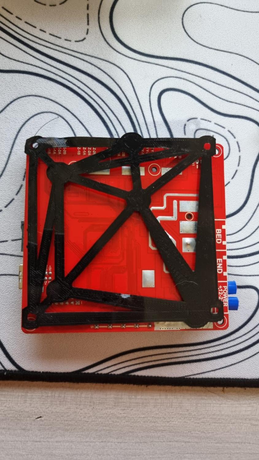
Salve a tutti, dopo aver avuto non poche difficoltá sono riuscito a far ripartire una anet a8 plus con una btt skr e3 v3.0 + TFT35 E3 V3.0.1 con marlin 2.0.9.5, ora anche io ho la mia prima stampante in 3d . (Se serve a qualcuno mi scrivesse) Ora ho classici dubbi da nabbetto. Come imposto correttamente tutta l'area di stampa in modo da stampare centralmente e senza che mi tagli centimetri dall'asse y o x? Ho notato stampando il classico cubetto che ho 2mm in meno nell'asse y, oltre a stamparlo decentrato, ma non di molto. Invece con il supporto per montare la skr al posto della scheda vecchia mi viene piú piccolo (come in foto) Grazie in anticipo
-
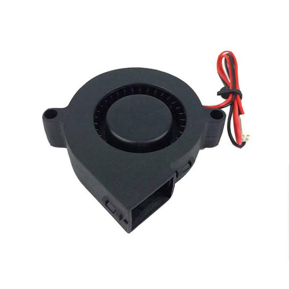
Salve a tutti, avrei bisogno di un consiglio, qual'é la migliore ventola sul fattore silenziositá in sostituzione a quella attuale per raffreddare il filamento? Di questo tipo 24v.
-
Anet a8 plus con skr mini e3 v3.0 endstop non funzionano
BND420 ha risposto a BND420 nella discussione Problemi generici o di qualità di stampa
scusate la risposta tardiva, mi da x min open y min TRIGGERED z min TRIGGERED (risolto) -
Anet a8 plus con skr mini e3 v3.0 endstop non funzionano
BND420 ha pubblicato una discussione in Problemi generici o di qualità di stampa
Salve a tutti, ho installato di recente sulla mia anet a8 plus una btt skr mini e3 v3.0 e attualmente sto controllando che tutto funzioni procendo a step, motori ok endstop non funzionanti, nessuno dei 3, il firmaware e' il 2.0.9.5, architettura é impostata su stm32g0 e l'enviroment é stm32g0b1re_btt questi sono i settings di configuration.h e sotto di configuration_adv.h, spero di aver riportato tutto, dove ho sbagliato? i cablaggi sono stati controllati piú volte e sembrano anche loro corretti #define DELTA_ENDSTOP_ADJ { 0.0, 0.0, 0.0 } // Get these values from G33 auto calibrate //=========================================================================== //============================== Endstop Settings =========================== //=========================================================================== // @section homing // Specify here all the endstop connectors that are connected to any endstop or probe. // Almost all printers will be using one per axis. Probes will use one or more of the // extra connectors. Leave undefined any used for non-endstop and non-probe purposes. #define USE_XMIN_PLUG #define USE_YMIN_PLUG #define USE_ZMIN_PLUG //#define USE_IMIN_PLUG //#define USE_JMIN_PLUG //#define USE_KMIN_PLUG //#define USE_XMAX_PLUG //#define USE_YMAX_PLUG //#define USE_ZMAX_PLUG //#define USE_IMAX_PLUG //#define USE_JMAX_PLUG //#define USE_KMAX_PLUG // Enable pullup for all endstops to prevent a floating state //#define ENDSTOPPULLUPS #if DISABLED(ENDSTOPPULLUPS) // Disable ENDSTOPPULLUPS to set pullups individually //#define ENDSTOPPULLUP_XMIN //#define ENDSTOPPULLUP_YMIN //#define ENDSTOPPULLUP_ZMIN //#define ENDSTOPPULLUP_IMIN //#define ENDSTOPPULLUP_JMIN //#define ENDSTOPPULLUP_KMIN //#define ENDSTOPPULLUP_XMAX //#define ENDSTOPPULLUP_YMAX //#define ENDSTOPPULLUP_ZMAX //#define ENDSTOPPULLUP_IMAX //#define ENDSTOPPULLUP_JMAX //#define ENDSTOPPULLUP_KMAX //#define ENDSTOPPULLUP_ZMIN_PROBE #define ENDSTOPPULLUP_ZMIN_PROBE #endif // Enable pulldown for all endstops to prevent a floating state //#define ENDSTOPPULLDOWNS #if DISABLED(ENDSTOPPULLDOWNS) // Disable ENDSTOPPULLDOWNS to set pulldowns individually //#define ENDSTOPPULLDOWN_XMIN //#define ENDSTOPPULLDOWN_YMIN //#define ENDSTOPPULLDOWN_ZMIN //#define ENDSTOPPULLDOWN_IMIN //#define ENDSTOPPULLDOWN_JMIN //#define ENDSTOPPULLDOWN_KMIN //#define ENDSTOPPULLDOWN_XMAX //#define ENDSTOPPULLDOWN_YMAX //#define ENDSTOPPULLDOWN_ZMAX //#define ENDSTOPPULLDOWN_IMAX //#define ENDSTOPPULLDOWN_JMAX //#define ENDSTOPPULLDOWN_KMAX //#define ENDSTOPPULLDOWN_ZMIN_PROBE #endif // Mechanical endstop with COM to ground and NC to Signal uses "false" here (most common setup). #define X_MIN_ENDSTOP_INVERTING true // Set to true to invert the logic of the endstop. #define Y_MIN_ENDSTOP_INVERTING false // Set to true to invert the logic of the endstop. #define Z_MIN_ENDSTOP_INVERTING false // Set to true to invert the logic of the endstop. #define I_MIN_ENDSTOP_INVERTING false // Set to true to invert the logic of the endstop. #define J_MIN_ENDSTOP_INVERTING false // Set to true to invert the logic of the endstop. #define K_MIN_ENDSTOP_INVERTING false // Set to true to invert the logic of the endstop. #define X_MAX_ENDSTOP_INVERTING false // Set to true to invert the logic of the endstop. #define Y_MAX_ENDSTOP_INVERTING false // Set to true to invert the logic of the endstop. #define Z_MAX_ENDSTOP_INVERTING false // Set to true to invert the logic of the endstop. #define I_MAX_ENDSTOP_INVERTING false // Set to true to invert the logic of the endstop. #define J_MAX_ENDSTOP_INVERTING false // Set to true to invert the logic of the endstop. #define K_MAX_ENDSTOP_INVERTING false // Set to true to invert the logic of the endstop. #define Z_MIN_PROBE_ENDSTOP_INVERTING true // Set to true to invert the logic of the probe. // Enable this feature if all enabled endstop pins are interrupt-capable. // This will remove the need to poll the interrupt pins, saving many CPU cycles. #define ENDSTOP_INTERRUPTS_FEATURE /** * Endstop Noise Threshold * * Enable if your probe or endstops falsely trigger due to noise. * * - Higher values may affect repeatability or accuracy of some bed probes. * - To fix noise install a 100nF ceramic capacitor in parallel with the switch. * - This feature is not required for common micro-switches mounted on PCBs * based on the Makerbot design, which already have the 100nF capacitor. * * :[2,3,4,5,6,7] */ //#define ENDSTOP_NOISE_THRESHOLD 2 // Check for stuck or disconnected endstops during homing moves. //#define DETECT_BROKEN_ENDSTOP //=========================================================================== //============================= Z Probe Options ============================= //=========================================================================== // @section probes // // See https://marlinfw.org/docs/configuration/probes.html // /** * Enable this option for a probe connected to the Z-MIN pin. * The probe replaces the Z-MIN endstop and is used for Z homing. * (Automatically enables USE_PROBE_FOR_Z_HOMING.) */ #define Z_MIN_PROBE_USES_Z_MIN_ENDSTOP_PIN // Force the use of the probe for Z-axis homing //#define USE_PROBE_FOR_Z_HOMING /** * Z_MIN_PROBE_PIN * * Define this pin if the probe is not connected to Z_MIN_PIN. * If not defined the default pin for the selected MOTHERBOARD * will be used. Most of the time the default is what you want. * * - The simplest option is to use a free endstop connector. * - Use 5V for powered (usually inductive) sensors. * * - RAMPS 1.3/1.4 boards may use the 5V, GND, and Aux4->D32 pin: * - For simple switches connect... * - normally-closed switches to GND and D32. * - normally-open switches to 5V and D32. */ //#define Z_MIN_PROBE_PIN 32 // Pin 32 is the RAMPS default /** * Z Servo Probe, such as an endstop switch on a rotating arm. */ //#define Z_PROBE_SERVO_NR 0 // Defaults to SERVO 0 connector. //#define Z_SERVO_ANGLES { 70, 0 } // Z Servo Deploy and Stow angles // Direction of endstops when homing; 1=MAX, -1=MIN // :[-1,1] #define X_HOME_DIR -1 #define Y_HOME_DIR -1 #define Z_HOME_DIR -1 //#define I_HOME_DIR -1 //#define J_HOME_DIR -1 //#define K_HOME_DIR -1 // @section machine // The size of the printable area #define X_BED_SIZE 300 #define Y_BED_SIZE 300 // Travel limits (mm) after homing, corresponding to endstop positions. #define X_MIN_POS -26 #define Y_MIN_POS -6 #define Z_MIN_POS 0 #define X_MAX_POS 300 #define Y_MAX_POS 297 #define Z_MAX_POS 350 //#define I_MIN_POS 0 //#define I_MAX_POS 50 //#define J_MIN_POS 0 //#define J_MAX_POS 50 //#define K_MIN_POS 0 //#define K_MAX_POS 50 /** * Software Endstops * * - Prevent moves outside the set machine bounds. * - Individual axes can be disabled, if desired. * - X and Y only apply to Cartesian robots. * - Use 'M211' to set software endstops on/off or report current state */ // Min software endstops constrain movement within minimum coordinate bounds #define MIN_SOFTWARE_ENDSTOPS #if ENABLED(MIN_SOFTWARE_ENDSTOPS) #define MIN_SOFTWARE_ENDSTOP_X #define MIN_SOFTWARE_ENDSTOP_Y //#define MIN_SOFTWARE_ENDSTOP_Z #define MIN_SOFTWARE_ENDSTOP_I #define MIN_SOFTWARE_ENDSTOP_J #define MIN_SOFTWARE_ENDSTOP_K #endif // Max software endstops constrain movement within maximum coordinate bounds #define MAX_SOFTWARE_ENDSTOPS #if ENABLED(MAX_SOFTWARE_ENDSTOPS) #define MAX_SOFTWARE_ENDSTOP_X #define MAX_SOFTWARE_ENDSTOP_Y #define MAX_SOFTWARE_ENDSTOP_Z #define MAX_SOFTWARE_ENDSTOP_I #define MAX_SOFTWARE_ENDSTOP_J #define MAX_SOFTWARE_ENDSTOP_K #endif #if EITHER(MIN_SOFTWARE_ENDSTOPS, MAX_SOFTWARE_ENDSTOPS) //#define SOFT_ENDSTOPS_MENU_ITEM // Enable/Disable software endstops from the LCD #endif /** * Filament Runout Sensors * Mechanical or opto endstops are used to check for the presence of filament. // Validate that endstops are triggered on homing moves #define VALIDATE_HOMING_ENDSTOPS configuration_adv.h: // If you want endstops to stay on (by default) even when not homing // enable this option. Override at any time with M120, M121. //#define ENDSTOPS_ALWAYS_ON_DEFAULT //#define DUAL_X_CARRIAGE #if HAS_X2_STEPPER && DISABLED(DUAL_X_CARRIAGE) //#define INVERT_X2_VS_X_DIR // X2 direction signal is the opposite of X //#define X_DUAL_ENDSTOPS // X2 has its own endstop #if ENABLED(X_DUAL_ENDSTOPS) #define X2_USE_ENDSTOP _XMAX_ // X2 endstop board plug. Don't forget to enable USE_*_PLUG. #define X2_ENDSTOP_ADJUSTMENT 0 // X2 offset relative to X endstop #endif #endif #if HAS_DUAL_Y_STEPPERS //#define INVERT_Y2_VS_Y_DIR // Y2 direction signal is the opposite of Y //#define Y_DUAL_ENDSTOPS // Y2 has its own endstop #if ENABLED(Y_DUAL_ENDSTOPS) #define Y2_USE_ENDSTOP _YMAX_ // Y2 endstop board plug. Don't forget to enable USE_*_PLUG. #define Y2_ENDSTOP_ADJUSTMENT 0 // Y2 offset relative to Y endstop #endif #endif // // Multi-Z steppers // #ifdef Z2_DRIVER_TYPE //#define INVERT_Z2_VS_Z_DIR // Z2 direction signal is the opposite of Z //#define Z_MULTI_ENDSTOPS // Other Z axes have their own endstops #if ENABLED(Z_MULTI_ENDSTOPS) #define Z2_USE_ENDSTOP _XMAX_ // Z2 endstop board plug. Don't forget to enable USE_*_PLUG. #define Z2_ENDSTOP_ADJUSTMENT 0 // Z2 offset relative to Y endstop #endif #ifdef Z3_DRIVER_TYPE //#define INVERT_Z3_VS_Z_DIR // Z3 direction signal is the opposite of Z #if ENABLED(Z_MULTI_ENDSTOPS) #define Z3_USE_ENDSTOP _YMAX_ // Z3 endstop board plug. Don't forget to enable USE_*_PLUG. #define Z3_ENDSTOP_ADJUSTMENT 0 // Z3 offset relative to Y endstop #endif #endif #ifdef Z4_DRIVER_TYPE //#define INVERT_Z4_VS_Z_DIR // Z4 direction signal is the opposite of Z #if ENABLED(Z_MULTI_ENDSTOPS) #define Z4_USE_ENDSTOP _ZMAX_ // Z4 endstop board plug. Don't forget to enable USE_*_PLUG. #define Z4_ENDSTOP_ADJUSTMENT 0 // Z4 offset relative to Y endstop #endif #endif #endif //#define SENSORLESS_BACKOFF_MM { 2, 2, 0 } // (mm) Backoff from endstops before sensorless homing #define HOMING_BUMP_MM { 5, 5, 2 } // (mm) Backoff from endstops after first bump #define HOMING_BUMP_DIVISOR { 2, 2, 4 } // Re-Bump Speed Divisor (Divides the Homing Feedrate) //#define HOMING_BACKOFF_POST_MM { 2, 2, 2 } // (mm) Backoff from endstops after homing //#define QUICK_HOME // If G28 contains XY do a diagonal move first //#define HOME_Y_BEFORE_X // If G28 contains XY home Y before X //#define HOME_Z_FIRST // Home Z first. Requires a Z-MIN endstop (not a probe). //#define CODEPENDENT_XY_HOMING // If X/Y can't home without homing Y/X first /** * Abort SD printing when any endstop is triggered. * This feature is enabled with 'M540 S1' or from the LCD menu. * Endstops must be activated for this option to work. */ //#define SD_ABORT_ON_ENDSTOP_HIT // M43 - display pin status, toggle pins, watch pins, watch endstops & toggle LED, test servo probe -
Anet A8 Plus: Motore Y vibra e non gira
BND420 ha risposto a BND420 nella discussione Problemi generici o di qualità di stampa
peró il problema dei cerchi rimaneva, come se avesse meno corsa dell'asse x, forse era sempre questione di settings peró é uscita di fabbrica con questo difetto.. comunque ora la modderó pesantemente visto che é gratis quindi non é piú un problema, sicuramente la scheda era l'ultima cosa peró amen. okok, avevo letto che la skr 3.0 usciva con marlin 2.0 preinstallato, vabbé non é un problema anzi meglio cosí, sta sera la monto e via -
Anet A8 Plus: Motore Y vibra e non gira
BND420 ha risposto a BND420 nella discussione Problemi generici o di qualità di stampa
speravo nel meglio, alla fine mi é stata regalata perché non stampava bene i cerchi, vado a provarla e smanettando probabilmente ho fottuto questi driver, da prima nell'autohome il piatto andava dal lato opposto, bisognava andare a premere il pulsante di fine corsa senno si mangiava i denti della cinghia e in stampa andava al contrario, non ero riuscito a fixarlo in nessuno modo, forse era un difetto di fabbrica alla fine ho solo peggiorato per la skr a livello di compatibilitá in teoria non dovrei avere problemi solo il doppio connettore sull'asse z ma ho visto che dalla 1.4 in poi sono presenti entrambi e dovrebbere essere plug and play (fino a una certa per via delle configurazioni) giusto? Sono abbastanza nuovo, é la mia prima 3d e anche facendo molte ricerche ho sempre dei dubbi (ovviamente dovró abbinarci lo schermo) Grazie comunque avevo bisogno di una conferma per i driver -
Anet A8 Plus: Motore Y vibra e non gira
BND420 ha pubblicato una discussione in Problemi generici o di qualità di stampa
Salve a tutti. Ho un'Anet A8 Plus con il motore dell'asse Y che non gira, ma vibra solamente. Ho fatto le seguenti prove: -Scambiato cavi tra i motori dell'asse X e Y. Il problema si é trasferito nel motore X, Y gira regolarmente -Scambiato i connettori X e Y nella board, ovvero mettere il motore X nell'asse Y e viceversa. Il problema si é trasferito nel motore X, Y gira regolarmente -Reinstallato bootloader (testato sia "Anet V1.0" sia "Anet V1.0 Optiboot") e firmware (Marlin 2.1.1) Il problema era presente anche con il firmware originale. Vorrei capire se devo cambiare la board e quindi optare per qualcosa di piú performante oppure provare ulteriori soluzioni, sia software sia hardware. Visivamente, sia i connettori sia le piste sulla scheda madre sembrano in ottime condizioni