

Tortuca67
-
Numero contenuti
14 -
Iscritto
-
Ultima visita
Tipo di contenuto
Profili
Articoli
Introduzione alla stampa 3D
Database materiali
Forum
Calendario
Blogs
Gallery
Download
Store
Risposte pubblicato da Tortuca67
-
-
Grazie Alep ,
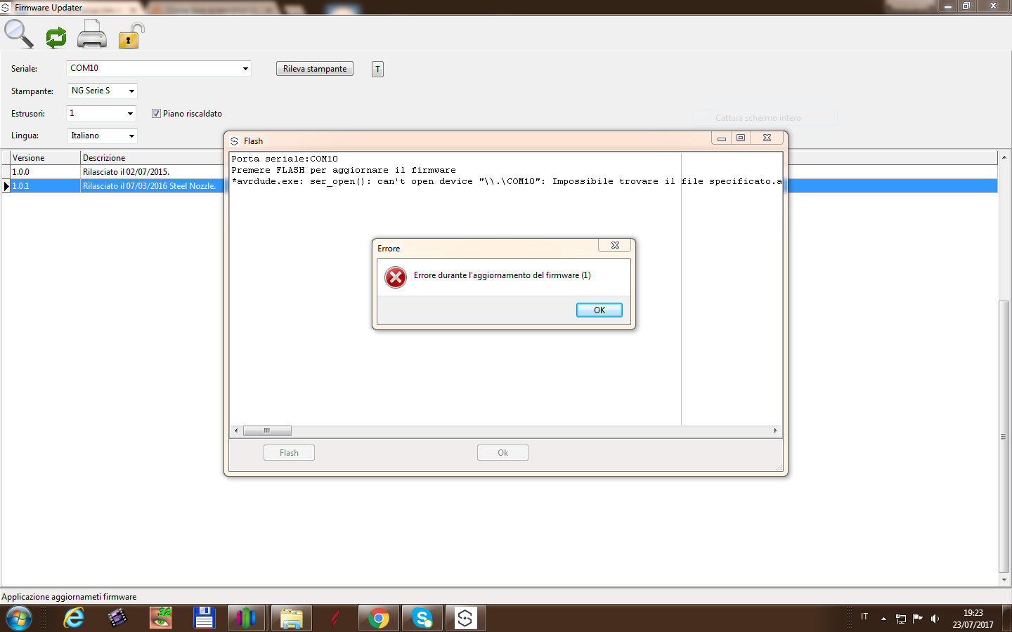
Cmq avevo già controllato e la porta com10 era già funzionante, tanto che la stampante funziona, ma non avevo mai provato ad aggiornarla...
-
Salve a tutti!
Ho deciso di montare il secondo estrusore sulla mia Sharebot NG ,così ho chiesto al supporto tecnico di Sharebot se era possibile, il quale mi ha risposto nessun problema e mi ha indicato cosa ordinare per aggiungere il secondo estrusore.Bene.. a leggere le spiegazioni del supporto tecnico sembrava una cosa semplice invece non è proprio così.Ho problemi con il programma Firmware Updater scaricato dal sito e non sono sicuro di dove mettere i cavi nella scheda.
Qualcuno di voi è riuscito nell'impresa? volevo capire dove sbaglio senza "stressare" il supporto tecnico di Sharebot .
grazie
Alessandro

-
Ciao ALep,
ecco la copia del file :
#ifndef CONFIGURATION_H
#define CONFIGURATION_H// This configurtion file contains the basic settings.
// Advanced settings can be found in Configuration_adv.h
// BASIC SETTINGS: select your board type, temperature sensor type, axis scaling, and endstop configuration//User specified version info of this build to display in [Pronterface, etc] terminal window during startup.
//Implementation of an idea by Prof Braino to inform user that any changes made
//to this build by the user have been successfully uploaded into firmware.
#define STRING_VERSION_CONFIG_H __DATE__ " " __TIME__ // build date and time
#define STRING_CONFIG_H_AUTHOR "(none, default config)" //Who made the changes.// SERIAL_PORT selects which serial port should be used for communication with the host.
// This allows the connection of wireless adapters (for instance) to non-default port pins.
// Serial port 0 is still used by the Arduino bootloader regardless of this setting.
#define SERIAL_PORT 0// This determines the communication speed of the printer
#define BAUDRATE 250000
//#define BAUDRATE 115200//// The following define selects which electronics board you have. Please choose the one that matches your setup
// 10 = Gen7 custom (Alfons3 Version) "https://github.com/Alfons3/Generation_7_Electronics"
// 11 = Gen7 v1.1, v1.2 = 11
// 12 = Gen7 v1.3
// 13 = Gen7 v1.4
// 3 = MEGA/RAMPS up to 1.2 = 3
// 33 = RAMPS 1.3 / 1.4 (Power outputs: Extruder, Bed, Fan)
// 34 = RAMPS 1.3 / 1.4 (Power outputs: Extruder0, Extruder1, Bed)
// 4 = Duemilanove w/ ATMega328P pin assignment
// 5 = Gen6
// 51 = Gen6 deluxe
// 6 = Sanguinololu < 1.2
// 62 = Sanguinololu 1.2 and above
// 63 = Melzi
// 64 = STB V1.1
// 7 = Ultimaker
// 71 = Ultimaker (Older electronics. Pre 1.5.4. This is rare)
// 8 = Teensylu
// 80 = Rumba
// 81 = Printrboard (AT90USB1286)
// 82 = Brainwave (AT90USB646)
// 9 = Gen3+
// 70 = Megatronics
// 90 = Alpha OMCA board
// 91 = Final OMCA board
// 101 = FELIXprinters electronics 2.0
// 301 = Rambo#ifndef MOTHERBOARD
#define MOTHERBOARD 101
#endif//// The following define selects which power supply you have. Please choose the one that matches your setup
// 1 = ATX
// 2 = X-Box 360 203Watts (the blue wire connected to PS_ON and the red wire to VCC)#define POWER_SUPPLY 1
//===========================================================================
//=============================Thermal Settings ============================
//===========================================================================
//
//--NORMAL IS 4.7kohm PULLUP!-- 1kohm pullup can be used on hotend sensor, using correct resistor and table
//
//// Temperature sensor settings:
// -2 is thermocouple with MAX6675 (only for sensor 0)
// -1 is thermocouple with AD595
// 0 is not used
// 1 is 100k thermistor - best choice for EPCOS 100k (4.7k pullup)
// 2 is 200k thermistor - ATC Semitec 204GT-2 (4.7k pullup)
// 3 is mendel-parts thermistor (4.7k pullup)
// 4 is 10k thermistor !! do not use it for a hotend. It gives bad resolution at high temp. !!
// 5 is 100K thermistor - ATC Semitec 104GT-2 (Used in ParCan) (4.7k pullup)
// 6 is 100k EPCOS - Not as accurate as table 1 (created using a fluke thermocouple) (4.7k pullup)
// 7 is 100k Honeywell thermistor 135-104LAG-J01 (4.7k pullup)
// 8 is 100k 0603 SMD Vishay NTCS0603E3104FXT (4.7k pullup)
// 9 is 100k GE Sensing AL03006-58.2K-97-G1 (4.7k pullup)
// 10 is 100k RS thermistor 198-961 (4.7k pullup)
//
// 1k ohm pullup tables - This is not normal, you would have to have changed out your 4.7k for 1k
// (but gives greater accuracy and more stable PID)
// 51 is 100k thermistor - EPCOS (1k pullup)
// 52 is 200k thermistor - ATC Semitec 204GT-2 (1k pullup)
// 55 is 100k thermistor - ATC Semitec 104GT-2 (Used in ParCan) (1k pullup)#define TEMP_SENSOR_0 1
#define TEMP_SENSOR_1 0
#define TEMP_SENSOR_2 0
#define TEMP_SENSOR_BED 1// Actual temperature must be close to target for this long before M109 returns success
#define TEMP_RESIDENCY_TIME 10 // (seconds)
#define TEMP_HYSTERESIS 3 // (degC) range of +/- temperatures considered "close" to the target one
#define TEMP_WINDOW 1 // (degC) Window around target to start the recidency timer x degC early.// The minimal temperature defines the temperature below which the heater will not be enabled It is used
// to check that the wiring to the thermistor is not broken.
// Otherwise this would lead to the heater being powered on all the time.
#define HEATER_0_MINTEMP 5
#define HEATER_1_MINTEMP 5
#define HEATER_2_MINTEMP 5
#define BED_MINTEMP 5// When temperature exceeds max temp, your heater will be switched off.
// This feature exists to protect your hotend from overheating accidentally, but *NOT* from thermistor short/failure!
// You should use MINTEMP for thermistor short/failure protection.
#define HEATER_0_MAXTEMP 275
#define HEATER_1_MAXTEMP 275
#define HEATER_2_MAXTEMP 275
#define BED_MAXTEMP 150// If your bed has low resistance e.g. .6 ohm and throws the fuse you can duty cycle it to reduce the
// average current. The value should be an integer and the heat bed will be turned on for 1 interval of
// HEATER_BED_DUTY_CYCLE_DIVIDER intervals.
//#define HEATER_BED_DUTY_CYCLE_DIVIDER 4// PID settings:
// Comment the following line to disable PID and enable bang-bang.
#define PIDTEMP
#define BANG_MAX 256 // limits current to nozzle while in bang-bang mode; 256=full current
#define PID_MAX 256 // limits current to nozzle while PID is active (see PID_FUNCTIONAL_RANGE below); 256=full current
#ifdef PIDTEMP
//#define PID_DEBUG // Sends debug data to the serial port.
//#define PID_OPENLOOP 1 // Puts PID in open loop. M104/M140 sets the output power from 0 to PID_MAX
#define PID_FUNCTIONAL_RANGE 10 // If the temperature difference between the target temperature and the actual temperature
// is more then PID_FUNCTIONAL_RANGE then the PID will be shut off and the heater will be set to min/max.
#define PID_INTEGRAL_DRIVE_MAX 255 //limit for the integral term
#define K1 0.5 //smoothing factor withing the PID
#define PID_dT ((16.0 * 8.0)/(F_CPU / 64.0 / 256.0)) //sampling period of the temperature routine// If you are using a preconfigured hotend then you can use one of the value sets by uncommenting it
// Ultimaker
#define DEFAULT_Kp 22.2
#define DEFAULT_Ki 1.08
#define DEFAULT_Kd 114// Makergear
// #define DEFAULT_Kp 7.0
// #define DEFAULT_Ki 0.1
// #define DEFAULT_Kd 12// Mendel Parts V9 on 12V
// #define DEFAULT_Kp 63.0
// #define DEFAULT_Ki 2.25
// #define DEFAULT_Kd 440
#endif // PIDTEMP// Bed Temperature Control
// Select PID or bang-bang with PIDTEMPBED. If bang-bang, BED_LIMIT_SWITCHING will enable hysteresis
//
// uncomment this to enable PID on the bed. It uses the same ferquency PWM as the extruder.
// If your PID_dT above is the default, and correct for your hardware/configuration, that means 7.689Hz,
// which is fine for driving a square wave into a resistive load and does not significantly impact you FET heating.
// This also works fine on a Fotek SSR-10DA Solid State Relay into a 250W heater.
// If your configuration is significantly different than this and you don't understand the issues involved, you proabaly
// shouldn't use bed PID until someone else verifies your hardware works.
// If this is enabled, find your own PID constants below.
//#define PIDTEMPBED
//
//#define BED_LIMIT_SWITCHING// This sets the max power delived to the bed, and replaces the HEATER_BED_DUTY_CYCLE_DIVIDER option.
// all forms of bed control obey this (PID, bang-bang, bang-bang with hysteresis)
// setting this to anything other than 256 enables a form of PWM to the bed just like HEATER_BED_DUTY_CYCLE_DIVIDER did,
// so you shouldn't use it unless you are OK with PWM on your bed. (see the comment on enabling PIDTEMPBED)
#define MAX_BED_POWER 256 // limits duty cycle to bed; 256=full current#ifdef PIDTEMPBED
//120v 250W silicone heater into 4mm borosilicate (MendelMax 1.5+)
//from FOPDT model - kp=.39 Tp=405 Tdead=66, Tc set to 79.2, argressive factor of .15 (vs .1, 1, 10)
#define DEFAULT_bedKp 10.00
#define DEFAULT_bedKi .023
#define DEFAULT_bedKd 305.4//120v 250W silicone heater into 4mm borosilicate (MendelMax 1.5+)
//from pidautotune
// #define DEFAULT_bedKp 97.1
// #define DEFAULT_bedKi 1.41
// #define DEFAULT_bedKd 1675.16// FIND YOUR OWN: "M303 E-1 C8 S90" to run autotune on the bed at 90 degreesC for 8 cycles.
#endif // PIDTEMPBED//this prevents dangerous Extruder moves, i.e. if the temperature is under the limit
//can be software-disabled for whatever purposes by
#define PREVENT_DANGEROUS_EXTRUDE
//if PREVENT_DANGEROUS_EXTRUDE is on, you can still disable (uncomment) very long bits of extrusion separately.
#define PREVENT_LENGTHY_EXTRUDE#define EXTRUDE_MINTEMP 170
#define EXTRUDE_MAXLENGTH (X_MAX_LENGTH+Y_MAX_LENGTH) //prevent extrusion of very large distances.//===========================================================================
//=============================Mechanical Settings===========================
//===========================================================================// Uncomment the following line to enable CoreXY kinematics
// #define COREXY// corse Endstop Settings
//#define ENDSTOPPULLUPS // Comment this out (using // at the start of the line) to disable the endstop pullup resistors#ifndef ENDSTOPPULLUPS
// fine Enstop settings: Individual Pullups. will be ignord if ENDSTOPPULLUPS is defined
//#define ENDSTOPPULLUP_XMAX
//#define ENDSTOPPULLUP_YMAX
//#define ENDSTOPPULLUP_ZMAX
//#define ENDSTOPPULLUP_XMIN
//#define ENDSTOPPULLUP_YMIN
//#define ENDSTOPPULLUP_ZMIN
#endif#ifdef ENDSTOPPULLUPS
#define ENDSTOPPULLUP_XMAX
#define ENDSTOPPULLUP_YMAX
#define ENDSTOPPULLUP_ZMAX
#define ENDSTOPPULLUP_XMIN
#define ENDSTOPPULLUP_YMIN
#define ENDSTOPPULLUP_ZMIN
#endif// The pullups are needed if you directly connect a mechanical endswitch between the signal and ground pins.
const bool X_ENDSTOPS_INVERTING = false; // set to true to invert the logic of the endstops.
const bool Y_ENDSTOPS_INVERTING = false; // set to true to invert the logic of the endstops.
const bool Z_ENDSTOPS_INVERTING = false; // set to true to invert the logic of the endstops.
#define DISABLE_MAX_ENDSTOPS// For Inverting Stepper Enable Pins (Active Low) use 0, Non Inverting (Active High) use 1
#define X_ENABLE_ON 0
#define Y_ENABLE_ON 0
#define Z_ENABLE_ON 0
#define E_ENABLE_ON 0 // For all extruders// Disables axis when it's not being used.
#define DISABLE_X false
#define DISABLE_Y false
#define DISABLE_Z false
#define DISABLE_E false // For all extruders// FelixPrinter settings Felix 1.0 revD up to Felix 2.0
#define INVERT_X_DIR true
#define INVERT_Y_DIR true
#define INVERT_Z_DIR true
#define INVERT_E0_DIR false
#define INVERT_E1_DIR false
#define INVERT_E2_DIR false// ENDSTOP SETTINGS:
// Sets direction of endstops when homing; 1=MAX, -1=MIN
#define X_HOME_DIR -1
#define Y_HOME_DIR -1
#define Z_HOME_DIR -1#define min_software_endstops false //If true, axis won't move to coordinates less than HOME_POS.
#define max_software_endstops false //If true, axis won't move to coordinates greater than the defined lengths below.
// Travel limits after homing
#define X_MAX_POS 255
#define X_MIN_POS 0
#define Y_MAX_POS 205
#define Y_MIN_POS 0
#define Z_MAX_POS 235
#define Z_MIN_POS 0#define X_MAX_LENGTH (X_MAX_POS - X_MIN_POS)
#define Y_MAX_LENGTH (Y_MAX_POS - Y_MIN_POS)
#define Z_MAX_LENGTH (Z_MAX_POS - Z_MIN_POS)// The position of the homing switches
//#define MANUAL_HOME_POSITIONS // If defined, MANUAL_*_HOME_POS below will be used
//#define BED_CENTER_AT_0_0 // If defined, the center of the bed is at (X=0, Y=0)//Manual homing switch locations:
#define MANUAL_X_HOME_POS 0
#define MANUAL_Y_HOME_POS 0
#define MANUAL_Z_HOME_POS 0//// MOVEMENT SETTINGS
#define NUM_AXIS 4 // The axis order in all axis related arrays is X, Y, Z, E
#define HOMING_FEEDRATE {50*60, 50*60, 4*60, 0} // set the homing speeds (mm/min)// default settings
#define DEFAULT_AXIS_STEPS_PER_UNIT {76.199904, 76.199904, 1600,169} // default steps per unit for Felix 2.0
#define DEFAULT_MAX_FEEDRATE {500, 500, 5, 25} // (mm/sec)
#define DEFAULT_MAX_ACCELERATION {5000,5000,100,80000} // X, Y, Z, E maximum start speed for accelerated moves. E default values are good for skeinforge 40+, for older versions raise them a lot.#define DEFAULT_ACCELERATION 1500 // X, Y, Z and E max acceleration in mm/s^2 for printing moves
#define DEFAULT_RETRACT_ACCELERATION 5000 // X, Y, Z and E max acceleration in mm/s^2 for r retracts// Offset of the extruders (uncomment if using more than one and relying on firmware to position when changing).
// The offset has to be X=0, Y=0 for the extruder 0 hotend (default extruder).
// For the other hotends it is their distance from the extruder 0 hotend.
// #define EXTRUDER_OFFSET_X {0.0, 20.00} // (in mm) for each extruder, offset of the hotend on the X axis
// #define EXTRUDER_OFFSET_Y {0.0, 5.00} // (in mm) for each extruder, offset of the hotend on the Y axis// The speed change that does not require acceleration (i.e. the software might assume it can be done instanteneously)
#define DEFAULT_XYJERK 10.0 // (mm/sec)
#define DEFAULT_ZJERK 0.4 // (mm/sec)
#define DEFAULT_EJERK 5.0 // (mm/sec)//===========================================================================
//=============================Additional Features===========================
//===========================================================================// EEPROM
// the microcontroller can store settings in the EEPROM, e.g. max velocity...
// M500 - stores paramters in EEPROM
// M501 - reads parameters from EEPROM (if you need reset them after you changed them temporarily).
// M502 - reverts to the default "factory settings". You still need to store them in EEPROM afterwards if you want to.
//define this to enable eeprom support
#define EEPROM_SETTINGS
//to disable EEPROM Serial responses and decrease program space by ~1700 byte: comment this out:
// please keep turned on if you can.
#define EEPROM_CHITCHAT//LCD and SD support
//#define ULTRA_LCD //general lcd support, also 16x2
//#define DOGLCD // Support for SPI LCD 128x64 (Controller ST7565R graphic Display Family)
//#define SDSUPPORT // Enable SD Card Support in Hardware Console//#define ULTIMAKERCONTROLLER //as available from the ultimaker online store.
#define ULTIPANEL //the ultipanel as on thingiverse// The RepRapDiscount Smart Controller (white PCB)
// http://reprap.org/wiki/RepRapDiscount_Smart_Controller
//#define REPRAP_DISCOUNT_SMART_CONTROLLER// The GADGETS3D G3D LCD/SD Controller (blue PCB)
// http://reprap.org/wiki/RAMPS_1.3/1.4_GADGETS3D_Shield_with_Panel
//#define G3D_PANEL//automatic expansion
#if defined(ULTIMAKERCONTROLLER) || defined(REPRAP_DISCOUNT_SMART_CONTROLLER) || defined(G3D_PANEL)
#define ULTIPANEL
#define NEWPANEL
#endif// Preheat Constants
#define PLA_PREHEAT_HOTEND_TEMP 195
#define PLA_PREHEAT_HPB_TEMP 55
#define PLA_PREHEAT_FAN_SPEED 0 // Insert Value between 0 and 255#define ABS_PREHEAT_HOTEND_TEMP 240
#define ABS_PREHEAT_HPB_TEMP 100
#define ABS_PREHEAT_FAN_SPEED 0 // Insert Value between 0 and 255
#ifdef ULTIPANEL
#define NEWPANEL //enable this if you have a click-encoder panel
#define SDSUPPORT
#define ULTRA_LCD
#ifdef DOGLCD // Change number of lines to match the DOG graphic display
#define LCD_WIDTH 20
#define LCD_HEIGHT 5
#else
#define LCD_WIDTH 20
#define LCD_HEIGHT 4
#endif
#else //no panel but just lcd
#ifdef ULTRA_LCD
#ifdef DOGLCD // Change number of lines to match the 128x64 graphics display
#define LCD_WIDTH 20
#define LCD_HEIGHT 5
#else
#define LCD_WIDTH 16
#define LCD_HEIGHT 2
#endif
#endif
#endif// Increase the FAN pwm frequency. Removes the PWM noise but increases heating in the FET/Arduino
#define FAST_PWM_FAN// M240 Triggers a camera by emulating a Canon RC-1 Remote
// Data from: http://www.doc-diy.net/photo/rc-1_hacked/
// #define PHOTOGRAPH_PIN 23// SF send wrong arc g-codes when using Arc Point as fillet procedure
//#define SF_ARC_FIX#include "Configuration_adv.h"
#include "thermistortables.h"#endif //__CONFIGURATION_H
grazie mille!!
Alessandro
-
Grazie ALEP,
Ho controllato e ricontrollato ma non va... evidentemente le mie competenze di marlin non sono sufficenti anche se dopo le tue spiegazioni ne capisco un pochino di più, può essere che il display sia rotto....
grazie
-
grazie Alep!, sempre gentile...
Questo è un estratto del mio Marlin, il mio display è un 20 *4
#ifdef ULTIPANEL
#define NEWPANEL //enable this if you have a click-encoder panel
#define SDSUPPORT
#define ULTRA_LCD
#ifdef DOGLCD // Change number of lines to match the DOG graphic display
#define LCD_WIDTH 20
#define LCD_HEIGHT 5
#else
#define LCD_WIDTH 20
#define LCD_HEIGHT 4
#endif
#else //no panel but just lcd
#ifdef ULTRA_LCD
#ifdef DOGLCD // Change number of lines to match the 128x64 graphics display
#define LCD_WIDTH 20
#define LCD_HEIGHT 5
#else
#define LCD_WIDTH 16
#define LCD_HEIGHT 2
#endif
#endif
#endif
In pratica devo capire qui se è tutto ok giusto?grazie
-
Ciao ALEP,
Ormai sono il tuo incubo....mi sono documentato a riguardo del LCD si vede che è alimentato perchè si accendono dei quadratini
, ma evidentemente non gli viene trasmesso alcun dato... tutte le spiegazioni sui forum sono molto tecniche , chiedo troppo se mi spieghi come inserire un Marlin per vedere se ne trovo uno che lo fa funzionare?grazie mille
-
Grazie Alep sempre disponibile e utile,
Ho fatto il solito casino collegando arduino alla stampante...non funzionava più
, poi con l'aiuto del forum di arduino e la tua risposta ho provato ad aggiornare il FW.
Come hai scritto non è difficile "se ti spiegano come fare" il display non funziona ancora
ma almeno la stampante è aggiornata e funzionante.
Alessandro
-
Salve Alep,
Seguendo i tuoi consigli per settare slic3r ora la stampante funziona egregiamente ,grazie, poi ho scoperto che per installare il display devo aggiornare il software su arduino , le istruzioni per l'aggiornamento non sono semplicissime da capire, pensi sia difficile per un "neofita"
di Arduino riuscire ad aggiornare il tutto??
grazie mille
-
Slic3r è dentro al programma repetier giusto? O stiamo parlando di altro programma...
Ho visto che hai passione e pazienza ... e rispondi a molti quesiti nel forum.ne approfitto a chiederti se l estrusore deve essere perfettamente perpendicolare al piano?
Perche nella mia stampante è leggermente inclinato? E non capisco se è un errore o voluto.
Grazie
-
Uso il programma scaricato dal sito della stampante "Repetier host".. stasera controllo i parametri (che ovviamente manco ho guardato ) e farò come mi hai suggerito i cubetti... sono partito in quarta pensando bastasse scaricate un oggetto da thingiverse e per magia premendo un tasto apparisse nel piatto......😆 ti terrò aggiornato...
Grazie
-
Si si i cavi sono 2 display e potenziometro... a sto punto sarà un problema di aggiornamento della scheda....cmq problema passato in secondo piano..ora sto impazzendo nel regolare l'estrusore.. non stampa uniforme.. cosa devo controllare la temperatura ,velocita di stampa o cosa?
Grazie mille per la risposta
Alessandro
-
Salve,
Ho acquistato una stampante felix 2.0 usata, la sto testando per capire come gira..qualcuno del forum la conosce?
Insieme alla stampante mi hanno dato un display da montare,basta inserire una spinetta ,ma la scheda non lo vede,va aggirnato qualcosa?
Grazie mille
-
Salve,
Un po per curiosità un po per distogliere il figlio (12 anni) dai videogiochi e dai vari youtuber.. ho acquistato una stampante 3d usata.. spero di aver fatto la scelta giusta.
Grazie
Alessandro da Vicenza
 , ma evidentemente non gli viene trasmesso alcun dato... tutte le spiegazioni sui forum sono molto tecniche , chiedo troppo se mi spieghi come inserire un Marlin per vedere se ne trovo uno che lo fa funzionare?
 , poi con l'aiuto del forum di arduino e la tua risposta ho provato ad aggiornare il FW.
 ma almeno la stampante è aggiornata e funzionante.
 di Arduino riuscire ad aggiornare il tutto??
Montaggio Secondo estrusore su NG
in Problemi generici o di qualità di stampa
Inviato
Ho risolto! Sarà utile a qualcun'altro...
Non riuscivo fare l'aggiornamento dal programma di sharebot perché tenevo occupata la stampante con simplify3d..spento il programma tutto è andato a buon fine. Cmq il Supporto tecnico di Sharebot è stato paziente e gentilissimo, mi hanno mandato una foto della scheda con la posizione dei cavi da installare e mi hanno seguito passo passo.
GRAZIE